Brash Imports .. to place an order for this or any item contact me at office@brashimports.com.au
Model 7588C (7") $ 165
Trade $ 175 Pickup/Posted
6169
(6")
$ 155 Trade $ 165 Pickup / Posted
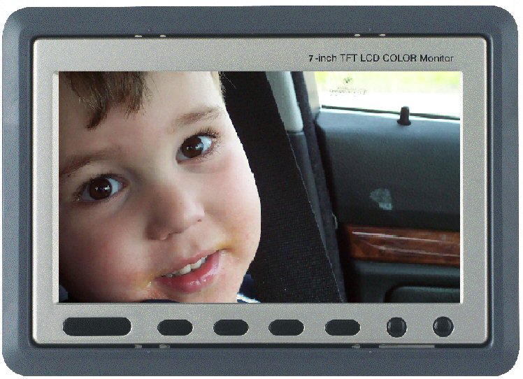
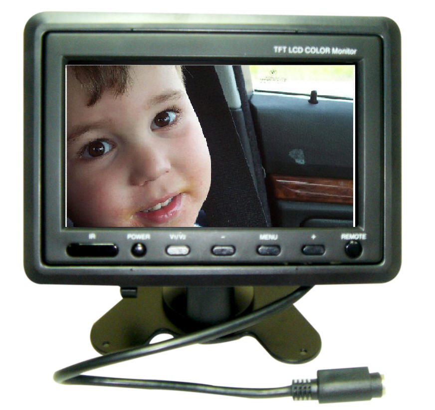
Headrest / Reversing Monitor with shroud and stand
6" or 7" Inch Headrest/mounting stand In-Car TFT LCD Monitor
Headrest or mounting stand 2 options design: up to yourself
Blue screen when no video signal
On screen display function menu
PAL/NTSC auto switch
Power supply:7W/12VDC
Image resolution: 7" 800 x 600 (1,440,000 pixels)
6" 720 x 480 ( 336,960 pixels)
Contrast: 300:1
Lum:
350cd/m2
View angel
range: (left/right)65 ° (top)40 ° (down)15°
Product size: 7" 195 x 140 x 35mm (W x H x D)
6" 170 x 130 x 33mm (W x H x D)
Color: Black as per image on the right.
This unit has a trigger wire which can be connected to the reverse lights.
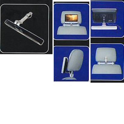
Head rest monitor adaptor
$20 each when sent with above monitors
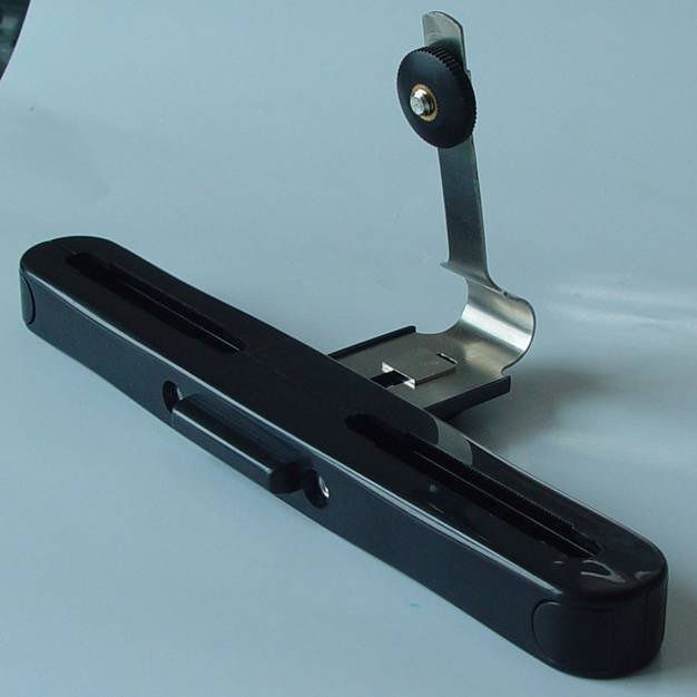
Features
Multi adaptors for head rest monitor. Will suit most vehicles
Eliminates the need for costly fitting, cutting etc - this monitor will need a small modification for the adaptors
Infrared Headphones
$45 when sent with above unit
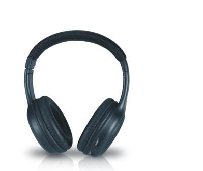
Light
weight headset for comfortable wearing
Automatic muting design on receiving headphones
Headphone Specifications:
FM system
carrier frequency:2.8MHz right channel, 2.3MHz left channel
Speaker: 40mm Mylar cone
Impedance: 32 ohms +/- 15%
Effective range (maximum): about 10 meters
Power source: batteries 2 x AAA
Battery life: about 48 hours .
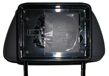
Headrest Monitor Installation notes. This is a generic copy of installation and may help in self installtions
|
GENERAL CABLE &
WIRING INFORMATION: |
|
INSTALLING LCD
MONITOR INTO HEADREST:
The Following Example is a BOSS BV-56M
Installed into a 97 Caravan Headrest |
|
|
|
|
Make your Measurements: Push on the headrest to make sure there are no obstructions that would prevent installation and to determine, if possible, how deep the metal support bracket is located. Mark the area to be cut on the headrest, use the back side of the housing as a template. |
Carefully cut the headrest using a sharp blade. YOU WILL BE MAKING AN “X” CUT IN THE HEADREST AND WILL NOT BE REMOVING THE OUTER UPHOLSTERY MATERIAL. DO NOT CUT THE SIDES, TOP OR BOTTOM. |
|
|
|
|
Start your cut ¼” from one inside corner and cut diagonally across, stopping ¼’ from the other corner. Repeat the procedure for the other two corners. You will end up with an “X” CUT in the template area. DO NOT REMOVE THE HEADREST OUTER UPHOLSTERY MATERIAL AT THIS TIME. The material will trimmed and folded back in for final installation after you remove the foam. |
Carefully peel back outer covering and start removing the foam inside the headrest. Cut to the depth required for the headrest housing you have. Stay 1/4'” inside from the edges and remove just enough foam so that the housing will fit snug. Insert the housing during the cutting to measure the fit and make adjustments as required. |
|
|
|
|
Trim headrest outer covering material, leave 1/2" to 3/4" material around the edge to be folded in when the housing is installed. In this application the headrest foam was removed down to the metal bracket because the bracket was only 1/2" deep into the headrest. |
Secure the plastic housing to the headrest using screws through the metal support. Drill holes in plastic housing if required. Drill a 3/4" hole in the metal support to allow the A/V cable to pass through. NOTE: if the metal support is deeper into the headrest you may not have to drill a hole for A/V cable. |
|
|
|
|
Make a small cut in the bottom of the headrest next to one of the support shafts. Pull A/V cable through housing and through hole in bottom of headrest. Install Monitor and conceal the A/V cable using split loom tubing or tie wrap to shaft. |
The A/V cable will have to be run through the seat back and out the bottom (running the cable through the seat back will vary). Secure the A/V cable so that it does not interfere with seat adjustment. Connect A/V cable to video and power source. If the seat is removable you can add a connector for power and ground wires so that the A/V cable can be unplugged allowing the seat to be removed. |
Camera Options
Camera Options:
OPTIONS
Base unit = 185 (6")
$195 (7")
then add
Camera options:
$ 50 CMOS Bullet Camera
$ 55 CMOS Bullet with I Red
$ 110 CCD Bullet Camera with I Red
$ 65 CMOS License plate
$ 70 CMOS License plate with I Red
$ 120 CCD License plate
$ 75 CMOS Square with I Red and Audio
$ 140 CCD Square with I Red and Audio
$ 75 CMOS Side View with I Red
$ 135 CCD Side View with I Red
$ 75 CMOS 150°Butterfly
$ 135 CCD 140° Butterfly
$ 70 CMOS Mini Bullet with I Red
finally
$ 5 For the first camera (5M
RCA cable)
$ 10 for the second camera (5m RCA + 10M RCA)
NB This monitor does not have audio
.jpg)
.jpg)
.jpg)
.jpg)
.jpg)
.jpg)
.jpg)